Define normal and alarm ranges
Start with the temperature and humidity limits of the equipment, then add realistic margin for site conditions. Use separate values for normal operation, early warning, and critical alarm.

Solutions
Turn enclosure temperature and humidity data into automated control, useful alarms, and faster maintenance decisions.
System purpose
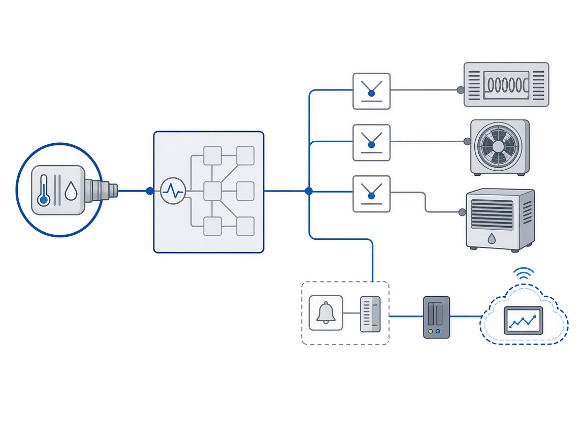
A sensor can tell you that humidity is rising or that temperature has moved outside the target range. It cannot prevent a failure unless it is connected to control logic, alarms, and a defined response.
A practical monitoring system answers three questions: What condition needs attention? What action should happen automatically? Who needs to know if the automatic response is not enough? That structure keeps the project focused on reliability instead of collecting data without a clear purpose.
Monitoring scope
The minimum set usually includes the conditions below. More advanced projects may also monitor door position, filter condition, current draw, external ambient conditions, or individual device health. The right scope depends on the cost of downtime, site accessibility, and whether the enclosure connects to a PLC, SCADA, BMS, or remote platform.
Control design
Start with the temperature and humidity limits of the equipment, then add realistic margin for site conditions. Use separate values for normal operation, early warning, and critical alarm.
Sensor location matters more than sensor quantity. A single sensor placed near a heater can show a comfortable temperature while sensitive equipment remains cold. Use representative locations near critical electronics but away from direct heat, in the air volume around the equipment, away from stagnant pockets and direct airflow, and accessible for inspection and replacement.
Relays can control heaters, dehumidifiers, fans, or alarm devices. The logic should use clear setpoints and hysteresis so the equipment does not switch excessively or create unstable conditions.
A local buzzer may be enough for a staffed facility. Remote cabinets usually need a signal to a PLC, SCADA, BMS, mobile network, or cloud platform.
Practical configurations
Best for accessible cabinets where maintenance staff can respond locally.
Best for distributed assets and sites that are difficult to inspect.
Best for projects already using PLC, SCADA, BMS, or a central monitoring platform.
Implementation
01
Identify the equipment and conditions that create the greatest reliability risk.
02
Define the normal, warning, and alarm ranges.
03
Select sensors and confirm representative installation locations.
04
Decide which actions should be automatic and which require human approval.
05
Confirm relay capacity, control voltage, wiring distance, and communication protocol.
06
Test alarms under simulated conditions before commissioning.
07
Review data after the first seasonal cycle and adjust settings if needed.

Telecom sites, energy-storage cabinets, and industrial enclosures often need automated control and remote alarms because physical inspection is infrequent or costly.
Why NOXT
NOXT provides temperature controllers, humidity controllers, hygrothermostats, and RS485-enabled control products for enclosure climate-control systems.
We support sensor selection, control logic, OEM/ODM configuration, and integration requirements for telecom, energy-storage, industrial, and infrastructure applications.
| Monitoring or control need | Recommended NOXT family | Role in the system |
|---|---|---|
| Basic temperature switching | KTS/KTO 011, ETY 011, ETR 011 | Switch heaters or fans at a preset temperature |
| Humidity-based switching | MF R012, EMFR 012, EFR 012, ETY 021, SK 3118 | Activate dehumidification or heating based on humidity |
| Combined temperature and humidity | ETF 012, ETY 031 | Monitor two conditions and control connected devices |
| Local alarm or relay output | Electronic controller with relay terminals | Trigger an indicator, PLC input, or alarm circuit |
| Remote or system integration | RS485-compatible controller option | Send data and status to a PLC, SCADA, BMS, or monitoring platform |
| Field visibility | Controller display and status indicators | Support commissioning, troubleshooting, and routine inspection |
Recommended solutions

Switch heaters or fans at preset temperature thresholds with relay outputs for local climate control.
View products
Activate dehumidification or heating based on humidity setpoints and measured cabinet conditions.
View products
Monitor temperature and humidity together and control connected heating or dehumidification devices.
View products
Send temperature, humidity, and status data to a PLC, SCADA, BMS, or remote monitoring platform.
View productsMost projects begin with internal temperature and relative humidity. Additional sensors depend on the equipment, site access, and cost of downtime.
No. Local relay control may be sufficient for accessible cabinets. RS485 is useful when data logging, remote monitoring, or system integration is required.
Set realistic thresholds, use hysteresis, verify sensor locations, and test the complete alarm path under normal and fault conditions.
No. Monitoring helps identify changing conditions and supports faster response, but inspections, cleaning, tightening, and component checks are still required.
NOXT can provide controllers and communication options for common integration requirements. Final compatibility should be confirmed against the site protocol, addressing, and wiring design.
Share the equipment list, site accessibility, required alarms, control devices, and existing communication system. Our engineers will help define a monitoring and control architecture that fits the project.
Please fill out the form below and we'll contact you as soon as possible.