
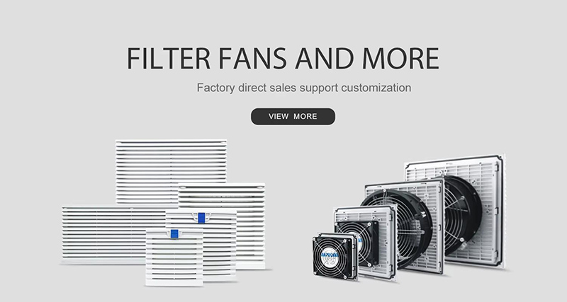
The airflow rating on a fan datasheet does not always reflect how much air will actually move through an electrical cabinet. These ratings are typically measured under free-air conditions, without the restrictions found in a real installation. Once intake and exhaust filters are added, airflow resistance increases and the fan may deliver considerably less air than its rated capacity.
That is why fan selection should start with the heat generated inside the cabinet and the airflow needed to remove it. From there, the key is finding a filter fan that can maintain sufficient airflow against the resistance of the installed system.
Why the Free-Blowing Rating Misleads
A free-blowing airflow rating is measured with no meaningful restriction at the fan inlet or outlet. It provides a useful starting point when comparing models, but it does not represent the airflow available inside a finished electrical cabinet. Once filters and enclosure openings are added, resistance increases and the effective airflow decreases.
How Outlet Filters Affect Cabinet Airflow
Filter mats help protect sensitive electrical components from dust, but they also create resistance to airflow. For example, our TB98 and TB99 120 mm filter fans deliver 105 m³/h at 50 Hz under free-blowing conditions.
When one outlet filter is installed, the listed airflow drops to 71 m³/h. Using two outlet filters increases it to 85 m³/h because the additional outlet area reduces back pressure. In the single-outlet configuration, the airflow reduction is approximately 32%. This is a normal effect of system resistance, not an indication of poor fan quality. It shows why cabinet ventilation should be sized using installed performance rather than the maximum catalog value.
Reading the Working Point Instead of the Peak
A fan performance curve shows how airflow decreases as static pressure increases. The enclosure has its own resistance curve, which rises as airflow increases. The intersection of these two curves is the operating point: the airflow the system can actually provide. As dust collects in the filter mat, resistance rises and the operating point shifts toward lower airflow. For outdoor installations or dusty environments, allowing an additional 20–30% capacity margin is a practical way to accommodate this change.
Work Out the Heat Load Before You Shop
Adding the Watts Inside
Start by calculating the heat dissipated by the equipment inside the cabinet, rather than adding up equipment nameplate power ratings. Variable frequency drives, power supplies, transformers, and busbars all contribute heat during operation. As an example, a 20-horsepower drive may dissipate around 750 W. Add the heat losses from each component, then include approximately 10% for wiring and terminal losses that may not be listed separately. If condensation is also a concern, the heater sizing article explains how enclosure heating fits into temperature and moisture control.
Picking a Delta T You Can Hold
Delta T (ΔT) is the difference between the target internal cabinet temperature and the temperature of the surrounding air. A shaded indoor control room may be able to maintain a 10 K difference under normal operating conditions. However, an outdoor cabinet exposed to direct sunlight may face additional solar heat gain, making a 5 K target difficult to achieve on a hot day. Select ΔT based on the highest expected site temperature and the actual enclosure conditions, not simply on the annual average ambient temperature.
Turn Heat Load into an Airflow Target
Once the heat load and allowable temperature difference are known, estimate the ventilation airflow required to remove the heat. A common approximation in imperial units is:
In metric units, the calculation is:
These calculations provide a sizing target; the selected fan must still meet that airflow after the filters and enclosure resistance are taken into account.
For example, if the cabinet produces 400 W of heat and the allowable temperature rise is 10 K, the required airflow is 120 m³/h. A 120 mm filter fan rated at 105 m³/h free blowing cannot meet that requirement, especially after an outlet filter is installed. In this case, consider a larger fan, additional outlet-filter area, or measures to reduce internal heat generation. Verifying the installed airflow before purchase helps avoid overheating during peak summer conditions.
Match the Target to a Filter Fan Size
| Series | Fan Size | Free Blowing at 50/60 Hz | With One Outlet Filter | Power Draw | Protection |
|---|---|---|---|---|---|
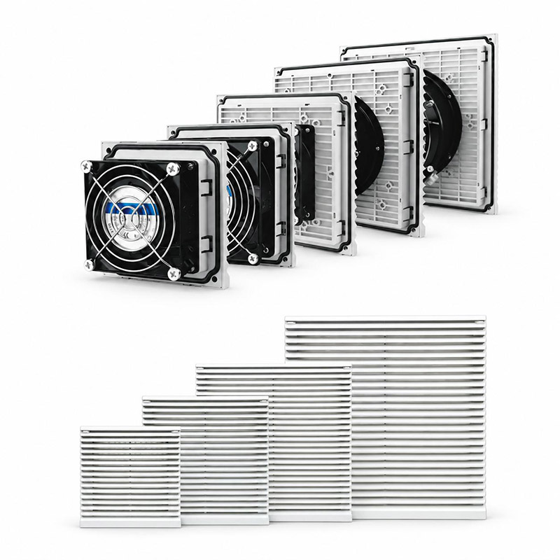
| TB98 / TB99 | 120 mm | 105/120 m³/h | 71/82 m³/h | 19/14 W | IP54 |
| TK88 | 120 mm | 105/120 m³/h | 71/82 m³/h | 19/14 W | IP54 |
| TK33 | 92 mm | 20/25 m³/h | 15/18 m³/h | 11/13 W | IP54 |
The TB98/TB99, TK88, and TK33 series use flame-retardant ABS housings rated UL94 V0, with IP54 protection and an operating temperature range of -10 to +55 °C. For smaller enclosures, the TK33 series filter fan provides a compact option and is also available in a 24 V DC version for applications without mains power at the cabinet door.
Put a Thermostat in the Circuit
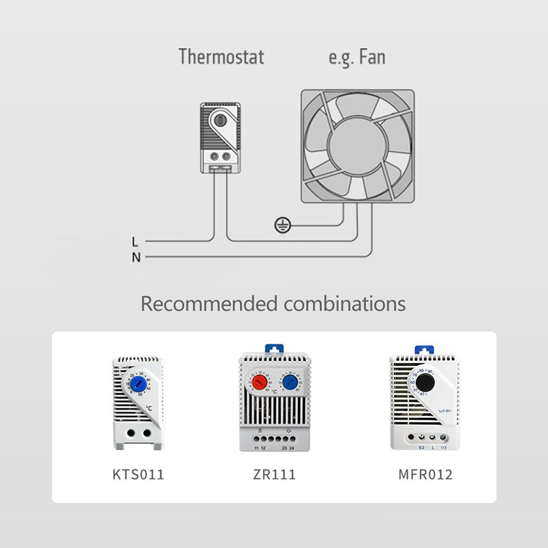
A cabinet cooling fan does not need to operate continuously in every application. Temperature-based control helps reduce unnecessary power consumption and filter wear while maintaining a suitable environment for electrical components. A thermostat switches the fan according to the actual cabinet temperature rather than a fixed operating schedule.
Normally Open for Cooling
For cooling applications, a normally open (NO) thermostat is generally the appropriate choice. Models such as the KTS011 keep the contact open below the switching temperature and close it as the cabinet warms, allowing the fan to start when cooling is needed. A normally closed (NC) device, such as our cabinet heater thermostat, is used for the opposite function: switching a heater on when the temperature falls. Choose the contact type according to whether the system needs to respond to rising or falling temperature.
Switching Difference and Cycling
The switching difference, also called the temperature differential, is the gap between the temperature at which the thermostat switches on and the temperature at which it switches off. For the KTS011, the specified switching difference is 7 K with a tolerance of ±4 K. A smaller differential gives tighter temperature control but may result in more frequent switching. A wider differential reduces cycling frequency while allowing a greater temperature variation inside the enclosure. The contact is rated for more than 100,000 switching cycles; nevertheless, the appropriate setting should reflect the cabinet’s thermal mass and operating requirements.
Where Installations Quietly Lose Airflow
Correct installation is just as important as choosing the right fan size. A common mistake is pairing a large intake fan with an outlet filter that provides insufficient free area. This increases back pressure and limits airflow. Dirty or blocked filter mats create the same problem over time, so an airflow figure of 71 m³/h with a clean filter may fall significantly after prolonged operation without maintenance.
Vent position also affects cooling performance. If both the intake and exhaust are installed low on the cabinet, warm air may remain trapped around equipment near the top. Where practical, position the intake lower and the exhaust higher to support effective air movement through the enclosure. If the design does not allow outside-air ventilation, axial fans can be used for internal air circulation, although circulation alone does not remove heat from the cabinet. During commissioning, check filter cleanliness, intake and outlet sizing, and the position of the ventilation openings.
Key Points
Free-blowing airflow is not the same as installed airflow; a single outlet filter can reduce the TB98/TB99 rating by about 32%.
Calculate heat loss and the allowable ΔT first, then select a fan that meets the resulting airflow requirement at its actual operating point.
Allow a 20–30% margin in outdoor or dusty installations to account for increasing filter resistance over time.
Use a normally open thermostat to control cooling fans, and consider the switching differential when setting up temperature control.
For support with product selection, share your cabinet dimensions, total internal heat dissipation, and expected ambient temperature range. Our engineering team can help recommend a suitable cabinet cooling fan set and review the relevant fan curve for your installation. You can also refer to our selection guide for a quicker overview of the sizing process.